Monday, April 13, 2015

Detection of Corrosion under Insulation Using Real Time Digital Radiography

Corrosion under insulation is a major industry problem because it is difficult to detect due mainly to the insulation cover masking potential flaws and/or flawed areas. 

These flaws can cause failures in areas that are not normally a primary focus of an inspection program. Failures can be costly at best and disastrous at their worst. With the real time digital radiography (DRT) scanner, both internal and external corrosion defects on stretches of pipe can be detected while the pipe remains in service without removing any insulation. DRT system consists of a radiation source and a linear array of radiation detectors, which are designed to examine insulated piping systems ranging from 4 to 24 inches (8 to 36 inches with insulation) in diameter and up to 3 inches thick.
During the detection process, a narrow beam of radiation is projected through the pipe walls and onto the detector array, positioned on the opposite side of the pipe. As the scanner moves along the pipe, data are acquired, and a color-coded image that depicts the relative thickness of the pipe wall is generated and displayed on the monitor in real time. Rail mounted DRT scanner has the ability to scan straight piping (in the vertical or horizontal position), elbows, and tees. A circumferential scanner can also be used to examine 100% of the piping in localized areas near elbows, tees, and other suspect areas. The system is sensitive enough to detect corrosion defects as small as 0.25 inch in diameter and 0.05 inch deep

BENEFITS:

• No removal of insulation required
• Thorough and quick scan of long sections of insulated pipe via rail mounted system
• Pipes can be examined while in service
• 100% circumferential volume examination possible
• Detects corrosion defects as small as 0.25 inch and 0.05 inch deep
• Real time detection
• Capable of scanning vertical and horizontal straight pipe runs, elbows and T-s
• Capable of scanning from 4” to 24” diameter pipe (excluding insulation)
• System is compact and easy to install

Source:http://www.ihiswt.com/sites/default/files/DRT%2009092011_0.pdf

Friday, April 3, 2015

Methods for mitigation of corrosion under insulation and other crevice corrosion

Corrosion of steel operating equipment and piping under insulation has been recognised as an important problem in the ammonia refrigeration, chilled water, chemical and petroleum industry.

Insulation is a necessary component and there to function in three ways: save energy, control process temperatures, and protect workers from high wall temperatures. The environment under insulation, the corrosion under insulation (CUI) environment, can be hot, wet, and promotes aggressive corrosion.
The American Petroleum Institute has directives that address the CUI problem and detail a program of identification, maintenance, and remediation. These directives, as well as efforts by professional societies (NACE and ASTM), promote the development of new solutions. The issue in achieving a good end result is that no clear solution exists for new installed piping as well as maintenance and remediation of existing installations.
NACE Standard RP0198-98 is an excellent source of information for preventing corrosion under insulation, but many corrosion engineers would agree that electrolytes will eventually find their way into even the best system. Selecting the right coating is extremely important. The coating is the last line of defence for keeping the electrolyte from the metal surface and preventing corrosion.
Recent coating innovations include a hydrophobic anti-corrosion gel that is tolerant of less than optimal surface preparation, is designed to keep the electrolyte away from the surface of the substrate, and also has the ability to neutralise the electrolyte if it breeches the vapour barrier and insulation.
Technology
The reactive anti-corrosion gel utilises mineralisation technology. Mineralisation is the ability to grow very thin minerals on metal surfaces for useful purposes.
The minerals are formed when reactants are delivered to the surface of the substrate, as shown in Figure 1.
How the reactive gel corrosion treatment works:
When the ferrous (steel) surface (1) is covered with a layer of reactive gel (2), the metal surface reacts with components in the gel to form a mineral layer (3). This thin glasslike layer (3) acts as a barrier between chlorides and the metal surface, thus providing corrosion resistance.
The mineral layer (3) has a thickness of 50–200 angstroms, only 0.01 per cent, or as thick as a piece of paper.
Although the thin mineral layer can be damaged by mechanical abuse, there is extra protection built into the system.
The presence and uniqueness of the mineralised layer can be confirmed by conventional analytical surface methods such as x-ray photoelectron spectroscopy or atomic force microscope (Figure 2 and Figure 3).
The anti-corrosion gel works in three basic ways:
Figure 1. A mineral formation; Figure 2. An untreated steel surface; Figure 3. A mineralised steel surface.
  1. Barrier system – the specially formulated products have great adhesion characteristics and are hydrophobic to help keep moisture away from the substrate.
  2. Buffering system – if moisture migrates through the gel, it is buffered to a high pH which is protective to steel piping.
  3. Mineralisation – growing an engineered surface, or surface conversion – creating a surface which resists corrosion even if moisture gets to it.
The anti-corrosion gel has a maximum service temperature of 350°F (177°C).
The mineralisation technology in the anti-corrosion gel has a history of solving unique corrosion problems. The first application of the mineralisation technology was by a major automotive supplier in a crevice corrosion application on strand of brake cables. The strand in sleeve design of the brake cable combined with the cyclical environment of heat and moisture creates a severe crevice corrosion environment. The technology has been used for over 30 years in this application, which has resulted in an increased service life and greater reliability.
The first non-automotive industrial application was with the United States Navy. Following successful laboratory, pier side, and shipboard demonstrations of the effectiveness of the gel in preventing crevice corrosion in anchor chain detachable link cavities, the US Navy in 1999 changed the Planned Maintenance System (PMS) to specify the use of a mineralising gel as the replacement for white lead and tallow in all surface ship anchor chain detachable links. Also in 1999, following extensive testing, the Navy issued MACHALT 526 which changed the design of the internals of weather deck watertight and airtight door dogging mechanisms. The basis for the change is the use of a mineralising lubricant inside the spindle sleeve in the door frame to stop the corrosion that had been the cause of dogging mechanism failure. The watertight door dogging mechanism corrosion problem was one of the top maintenance issues for the fleet. In May 2002 a second MACHALT, 544, was approved to apply the same technology to ballistic type dogs in three watertight doors in DDG-51 Class ships. These solutions represented a significant saving for the fleet.
The gel has years of history on CUI applications in the food and beverage industry. It has also been used as an anti-corrosion coating in well head casings, on pig doors, structural steel, tank chimes, ammonia systems, vessels, and as flange filler. Field trials are currently underway to further evaluate this technology in areas where it is cost prohibitive to achieve optimal surface preparation.

Source:http://pipeliner.com.au/news/methods_for_mitigation_of_corrosion_under_insulation_and_other_crevice_corr/80887

Tuesday, March 10, 2015

Corrosion of Carbon Steel in Sour Water From the Oil Industry

Among the corrosion problems, one of the most important present in the refining oil industry, is specifically the related to the sour water generated in primary distillation plants. Despite the efforts made in the industrial field, and in fundamental studies; the different operating conditions as well as different concentrations of pollutants, makes their control very complicated. 

The studies that have been trying to simulate the operating conditions in sour waters have increased in the last ten years, in which the characteristics of the raw obtained, have changed resulting in corrosive environments much more aggressive than before. The purpose of these studies was to try to find ways, in which various agents affect or minimize corrosion, with the purpose of determining the predominant mechanism of corrosion in such environments. 

On the other hand, carbon steel AISI 1018 is widely used as construction material in many industries due to its excellent mechanical properties and low cost . So, the evaluation of carbon steel corrosion in H2S environments is very important in the petroleum industry, as this phenomenon is responsible for costly social, economic and sometimes even human losses . The sour water is considered as waste water containing sulfides and chlorides, among other components; this kind of water is very harmful to metallic equipments that are in contact with it, producing high corrosion rates leading to failures and material drainage and spilling . An important factor involved in the process of corrosion, is the temperature, because the corrosion rate increases as the temperature increase in the corrosion medium on the reactions proceeding in pure acids.

However, this does not happen in all systems, for example, the steel AISI 304 SS; results indicated higher corrosion at high temperatures (more than 75 ºC), but at mid temperatures (between 50 and 75 ºC) corrosion rates were similar; and at low or moderate temperatures (between 25 and 50 ºC), the stainless steels are in true passive state below the transpasive region. From early studies in the same work on the corrosion behaviour of AISI 304 using anodic polarization method, it was observed, a smaller passive range at higher temperature and hence an unstable passive film. Finally, failures due to wet H2S cracking have been experienced extensively in production operations, in refining and in pipelines. Many commonly used steels and alloys are susceptible to cracking under the prevailing high temperatures, pressures and stresses.

Source:http://www.electrochemsci.org/papers/vol6/6105016.pdf

Monday, March 2, 2015

CORROSION PROBLEMS IN PETROLEUM INDUSTRY

Corrosion costs of the oil industry are billions of dollars in a year. Corrosion affects every aspect of exploration and production, from offshore rigs to casing. Methods of control and techniques to monitor corrosion, along with an explanation of the chemical causes of corrosion are discussed.

Corrosion in petroleum industry
The Petroleum industry contains a wide variety of corrosive environments. Some of these are unique to this industry. Thus it is convenient to group all these environments together. Corrosion problems occur in the petroleum industry in at least three general areas: 
(1) production
(2) transportation and storage
(3) refinery operations.

Production 
Oil and gas fields consume a tremendous amount of iron and steel pipe, tubing, pumps, valves, and sucker rods. Leaks cause loss of oil and gas and also permit infiltration of water and silt, thus increasing corrosion damage. Saline water and sulphides are often present in oil and gas wells. Corrosion in wells occurs inside and outside the casing. Surface equipment is subject to atmospheric corrosion. In secondary recovery operations, water is pumped into the well to force up the oil. 

Transportation and storage 
Petroleum products are transported by tankers, pipelines, railway tank cars, and tank trucks. The outside submerged surfaces of tanks on the outside surface of underground pipeline s are protected with coatings and by using cathodic protection. Cathodic protection is also applied to the inside of tankers to prevent corrosion by seawater used for washing or ballast. Gasoline-carrying tankers present a more severe internal corrosion problem than oil tanks because the gasoline keeps the metal too clean. Oil leaves a film that affords some protection. Tank cars and tank trucks are coated on the outside for atmospheric corrosion. The main reason for internal corrosion of storage tanks is the presence of water which settles and remains on the bottom. Coatings and cathodic protection are used. Alkaline sodium chromate (or sodium nitrate) has been found to be an effective inhibitor for corrosion of domestic fuel oil tanks. Internal corrosion of product pipelines can be controlled with coatings and inhibitors (a few parts per million) such as amines and nitrites. Ingenious methods for coating pipelines in place underground have also been developed. 

Refinery operations 
Most of the corrosion difficulties in refineries are due to inorganics such as water, H2S, CO2, sulfuric acid, and sodium chloride, and not to the organics themselves. For this reason, the petroleum industry has much in common with the chemical industry. Corrosive agents may be classified into two general categories: (1) those present in feedstock or crude oil, and (2) those associated with processes or control. Water is usually present in crude oils, and complete removal is difficult. Water acts as an electrolyte and causes corrosion. It also tends to hydrolyze other materials, particularly chlorides, and thus forms an acidic environment.

Source:file:///C:/Users/HQ0201/Downloads/1334-4359-1-PB%20santhana%20petroleum.pdf

Wednesday, February 18, 2015

A Primer on Sulfidation Corrosion

High temperature sulfidation is probably the most well-known corrosion mechanism in the oil refining industry because it occurs in large sections of the refinery.  Sulfidation corrosion (also known as sulfidic corrosion) is a result of naturally occurring sulfur (S) compounds found in crude oil.  In the absence of hydrogen, corrosion due to sulfur compounds in the crude is thought to occur at temperatures above 500F (260C).  Up to that temperature, corrosion rates due to sulfidation are relatively low, even for carbon steels, unless there is naphthenic acid present in the crude.  

Sulfidation corrosion results in the thinning of the pressure containment envelope, affecting such components as piping and pipe fittings, heater tubes, and pressure vessels.  Most industry incidents have occurred in piping, due to lower nominal wall thicknesses as compared to other equipment types.  Sulfidation corrosion can be localized or general in nature for a given component, though the majority of cases exhibit general thinning.   

When the damage is general and thinning occurs over a large area, ruptures are possible and can lead to the potential release of large quantities of hydrocarbon streams. Corrosive thinning of piping walls and equipment due to sulfidation depends on many factors, such as sulfur content of the oil, temperature, flow rate, and H2 concentration, making it hard to predict accurately. However, one predictor of higher sulfidation rates is low silicon content in carbon steel components. 

Susceptible Areas

According to the American Petroleum Institute (API) Recommended Practice 939-C (Guidelines for Avoiding Sulfidation Corrosion Failures in Oil Refineries), one-third of high-temperature sulfidic corrosion failures are the result of low silicon content in piping. Moreover, older pipe with low Si may corrode at rates 2 to 10 times faster than surrounding higher Si piping. Recent industry experience indicates that carbon steel components (primarily pipe) and their respective welds with low-Si (< 0.10 wt. %) content can corrode at an accelerated rate when exposed to H2-free sulfidation corrosion conditions. Piping welds, where the root passes were made with low-Si containing filler metals, have been shown to corrode at a greater rate than the base metal components when exposed to the same process conditions.

Source:https://inspectioneering.com/tag/sulfidation

Friday, February 13, 2015

Portable Pipe Wall Thickness Measuring Technique "CUI Exposed"

One of the greatest challenges facing many of the process industries; namely the petrochemical, refining, fossil power, and pulp and paper industries is: How to effectively examine their insulated piping?

While there are a number of failure mechanisms involved in various process piping systems, piping degradation through corrosion and erosion are by far the most prevalent. This degradation can be in the form of external corrosion under insulation (CUI), internal corrosion through a variety of mechanisms, and internal erosion caused by the flow of the product through the pipe.

Refineries, chemical plants and electrical power plants have MANY thousands of miles of pipe that are insulated to prevent heat loss or heat absorption. This insulation is often made up of several materials, with calcium based material being the most dense. The insulating material is usually wrapped with an aluminum or stainless steel outer wrap.

A partial sampling of the most popularly used detection techniques are described as follows. As with anything, they have caveats, benefits, and limitations. Check with your NDE specialist to make sure you understand the availability, limitations, and benefits of the various options.

Brute forcing

The least complex way to detect CUI, brute forcing involves simply stripping the insulation off of the equipment and examining it for corrosion. This is a comparatively time-consuming, fairly expensive work process, especially if the insulation contains asbestos, so it may not be suitable for all situations.

Conventional radiography

This is the most common NDE technique used for detecting CUI without insulation removal. Conventional radiography involves a process where radioactive rays are directed at the object to be inspected, passing through it and capturing the image on a silver halide film to be examined. It has numerous advantages, including: it can be used with insulation of any thickness or type, through many types of internal product (some cases might require very high radiation sources), on pipes of varying diameters, and on both thick and thin wall pipes. Check with your NDE specialist to make sure conditions permit a valid “shot”.

Digital radiography

As opposed to conventional radiography, digital radiography relies on exposing reusable storage phosphor screens as an alternative traditional silver halide film. This allows the information to be stored digitally, saving both time and storage space. It also requires less radiation due to the phosphor film and therefore has a reduced impact on the safety compared to conventional radiography. Consult with your radiation safety specialist to make sure you fully understand the safety impact prior to establishing the Safe Zone.

Low intensity x-ray

The low-intensity x-ray imaging scope is a hand-held, totally portable fluoroscopic device utilizing a low-energy, low-intensity gamma source of Iridium. This can be a very quick way of qualitatively screening pipe for CUI. Iridum-192 is a typical radiation source for this technique.

Pulsed eddy current (PEC)

This method has been used in corrosion detection for several years and is highly useful in situations where an object’s surface is rough or inaccessible. Moreover, this method does not require surface preparation or the removal of insulation, thus it can be a quick and cost-effective solution for corrosion detection. The method works by sending out a pulsed magnetic field via probe coil, which penetrates through the non-magnetic insulation between the probe and the object being inspected. This will induce eddy currents that can be measured to determine whether or not corrosion is present.

Guided-wave ultrasonics (GWUT)

This method of testing involves sending guided waves out along the axial direction of a pipe and then measuring the reflections for echoes, which might be caused by corrosion. The main advantage of this method is that it is possible to inspect supports that are not directly accessible for visual inspection. The downside of the method though is that the actual accuracy of the results are strongly dependent on how good the inspector and the testing procedures used are; thus an inexperienced inspector can lead to inaccurate results.

Ultrasonic thickness measurements

This process can be used to determine the external condition of vessels and remaining thickness of piping components. It works by sending ultrasonic waves into the surface of the object and measuring the time taken by the wave to return to the surface. It is a fairly simple technique. However, it does require adequate contact with the material, so it is not viable for every situation.

Other techniques, such as neutron back scatter and infrared thermography, can help to find moisture under insulation, which may then help detect where CUI is occurring as well. These methods infer that there is potential CUI activity, as opposed to directly detecting metal loss or cracking


Source:https://inspectioneering.com/journal/1999-01-01/387/portable-pipe-wall-thickness-m

Monday, February 9, 2015

New Inspection Tool - Corrosion Under Insulation (CUI)

In May 1995, Omega International Technology, Inc., began testing a new system to measure pipe wall thickness using digital radiography (RT) scanning. This new system has the potential for being faster, less labor intensive, and shown improved accuracy over traditional ultrasound testing, and at a lower cost. Perhaphs best of all, scanning can be performed while the pipe is in service, insulation in place.
Digital radiography refers to the process of producing and analyzing X-Ray images using electronic devices instead of traditional film. For twenty years difital radiography, in the form of Computed Tomography (CT) scanners have been used to peer inside the human body. In the past decade, digital readiography has been used to inspect critical components for military and industrial applications. Even more recently, systems employing digital radiography are being used on processing lines in the food industry as an integral part of their quality assurance programs.
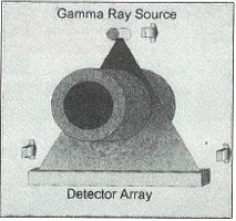
The concept behind digital radiography is similar to taking an X-Ray at a doctors office. A source, such as an X-Ray tube, sends a beam of high energy photons through the object of interest (see Figure 1). Some of the photons are absorbed by the object and the rest pass through it. The relative number of photons that are absorbed is directly related to the amount of material in the path of the photons. On the other side of the object, an array of defectors measure the number of photons passing through (the signal), producing an image on the inside of the object.
Figure 1
Traditionally, digital radiography has employed X-Rays to pass trhough objects, as opposed to other types of photons, such as Gamma Rays. X-Ray generating systems are bulky, require electricity, and are not very portable. Readioactive isotopes, however, are small, inexpensive, and easy to maintain. Unfortunately, readioactive isotopoes also tend to release much less energy than X-Ray systems. Most conventional detectors do not have the sensitivity to use radioactive isotopes to produce images. A new generation of detectors developed by Omega, however, are able to use very low intensity Gamma ray signals to measure pipe wall thicknesses.
The system employs an Iridium[+192] Gamma ray source and the new scintillator-based detectors instead of an X-Ray system and traditional detectors (see Figure 2). Coupled with a portable computer system, running data analysis and storage software, the entire system is mounted onto a pipeline and allowed to travel under its own power along the length of the pipe. The system automatically scans the pipe and computes the pipe wall thickness.
Figure 2
Source:https://inspectioneering.com/journal/1995-09-01/70/new-inspection-tool---corrosio

Happy Deepavali

The festival of light is here! May you be the happiest and may love be always with you. Happy Deepavali!