Wednesday, February 18, 2015

A Primer on Sulfidation Corrosion

High temperature sulfidation is probably the most well-known corrosion mechanism in the oil refining industry because it occurs in large sections of the refinery.  Sulfidation corrosion (also known as sulfidic corrosion) is a result of naturally occurring sulfur (S) compounds found in crude oil.  In the absence of hydrogen, corrosion due to sulfur compounds in the crude is thought to occur at temperatures above 500F (260C).  Up to that temperature, corrosion rates due to sulfidation are relatively low, even for carbon steels, unless there is naphthenic acid present in the crude.  

Sulfidation corrosion results in the thinning of the pressure containment envelope, affecting such components as piping and pipe fittings, heater tubes, and pressure vessels.  Most industry incidents have occurred in piping, due to lower nominal wall thicknesses as compared to other equipment types.  Sulfidation corrosion can be localized or general in nature for a given component, though the majority of cases exhibit general thinning.   

When the damage is general and thinning occurs over a large area, ruptures are possible and can lead to the potential release of large quantities of hydrocarbon streams. Corrosive thinning of piping walls and equipment due to sulfidation depends on many factors, such as sulfur content of the oil, temperature, flow rate, and H2 concentration, making it hard to predict accurately. However, one predictor of higher sulfidation rates is low silicon content in carbon steel components. 

Susceptible Areas

According to the American Petroleum Institute (API) Recommended Practice 939-C (Guidelines for Avoiding Sulfidation Corrosion Failures in Oil Refineries), one-third of high-temperature sulfidic corrosion failures are the result of low silicon content in piping. Moreover, older pipe with low Si may corrode at rates 2 to 10 times faster than surrounding higher Si piping. Recent industry experience indicates that carbon steel components (primarily pipe) and their respective welds with low-Si (< 0.10 wt. %) content can corrode at an accelerated rate when exposed to H2-free sulfidation corrosion conditions. Piping welds, where the root passes were made with low-Si containing filler metals, have been shown to corrode at a greater rate than the base metal components when exposed to the same process conditions.

Source:https://inspectioneering.com/tag/sulfidation

Friday, February 13, 2015

Portable Pipe Wall Thickness Measuring Technique "CUI Exposed"

One of the greatest challenges facing many of the process industries; namely the petrochemical, refining, fossil power, and pulp and paper industries is: How to effectively examine their insulated piping?

While there are a number of failure mechanisms involved in various process piping systems, piping degradation through corrosion and erosion are by far the most prevalent. This degradation can be in the form of external corrosion under insulation (CUI), internal corrosion through a variety of mechanisms, and internal erosion caused by the flow of the product through the pipe.

Refineries, chemical plants and electrical power plants have MANY thousands of miles of pipe that are insulated to prevent heat loss or heat absorption. This insulation is often made up of several materials, with calcium based material being the most dense. The insulating material is usually wrapped with an aluminum or stainless steel outer wrap.

A partial sampling of the most popularly used detection techniques are described as follows. As with anything, they have caveats, benefits, and limitations. Check with your NDE specialist to make sure you understand the availability, limitations, and benefits of the various options.

Brute forcing

The least complex way to detect CUI, brute forcing involves simply stripping the insulation off of the equipment and examining it for corrosion. This is a comparatively time-consuming, fairly expensive work process, especially if the insulation contains asbestos, so it may not be suitable for all situations.

Conventional radiography

This is the most common NDE technique used for detecting CUI without insulation removal. Conventional radiography involves a process where radioactive rays are directed at the object to be inspected, passing through it and capturing the image on a silver halide film to be examined. It has numerous advantages, including: it can be used with insulation of any thickness or type, through many types of internal product (some cases might require very high radiation sources), on pipes of varying diameters, and on both thick and thin wall pipes. Check with your NDE specialist to make sure conditions permit a valid “shot”.

Digital radiography

As opposed to conventional radiography, digital radiography relies on exposing reusable storage phosphor screens as an alternative traditional silver halide film. This allows the information to be stored digitally, saving both time and storage space. It also requires less radiation due to the phosphor film and therefore has a reduced impact on the safety compared to conventional radiography. Consult with your radiation safety specialist to make sure you fully understand the safety impact prior to establishing the Safe Zone.

Low intensity x-ray

The low-intensity x-ray imaging scope is a hand-held, totally portable fluoroscopic device utilizing a low-energy, low-intensity gamma source of Iridium. This can be a very quick way of qualitatively screening pipe for CUI. Iridum-192 is a typical radiation source for this technique.

Pulsed eddy current (PEC)

This method has been used in corrosion detection for several years and is highly useful in situations where an object’s surface is rough or inaccessible. Moreover, this method does not require surface preparation or the removal of insulation, thus it can be a quick and cost-effective solution for corrosion detection. The method works by sending out a pulsed magnetic field via probe coil, which penetrates through the non-magnetic insulation between the probe and the object being inspected. This will induce eddy currents that can be measured to determine whether or not corrosion is present.

Guided-wave ultrasonics (GWUT)

This method of testing involves sending guided waves out along the axial direction of a pipe and then measuring the reflections for echoes, which might be caused by corrosion. The main advantage of this method is that it is possible to inspect supports that are not directly accessible for visual inspection. The downside of the method though is that the actual accuracy of the results are strongly dependent on how good the inspector and the testing procedures used are; thus an inexperienced inspector can lead to inaccurate results.

Ultrasonic thickness measurements

This process can be used to determine the external condition of vessels and remaining thickness of piping components. It works by sending ultrasonic waves into the surface of the object and measuring the time taken by the wave to return to the surface. It is a fairly simple technique. However, it does require adequate contact with the material, so it is not viable for every situation.

Other techniques, such as neutron back scatter and infrared thermography, can help to find moisture under insulation, which may then help detect where CUI is occurring as well. These methods infer that there is potential CUI activity, as opposed to directly detecting metal loss or cracking


Source:https://inspectioneering.com/journal/1999-01-01/387/portable-pipe-wall-thickness-m

Monday, February 9, 2015

New Inspection Tool - Corrosion Under Insulation (CUI)

In May 1995, Omega International Technology, Inc., began testing a new system to measure pipe wall thickness using digital radiography (RT) scanning. This new system has the potential for being faster, less labor intensive, and shown improved accuracy over traditional ultrasound testing, and at a lower cost. Perhaphs best of all, scanning can be performed while the pipe is in service, insulation in place.
Digital radiography refers to the process of producing and analyzing X-Ray images using electronic devices instead of traditional film. For twenty years difital radiography, in the form of Computed Tomography (CT) scanners have been used to peer inside the human body. In the past decade, digital readiography has been used to inspect critical components for military and industrial applications. Even more recently, systems employing digital radiography are being used on processing lines in the food industry as an integral part of their quality assurance programs.
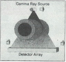
The concept behind digital radiography is similar to taking an X-Ray at a doctors office. A source, such as an X-Ray tube, sends a beam of high energy photons through the object of interest (see Figure 1). Some of the photons are absorbed by the object and the rest pass through it. The relative number of photons that are absorbed is directly related to the amount of material in the path of the photons. On the other side of the object, an array of defectors measure the number of photons passing through (the signal), producing an image on the inside of the object.
Figure 1
Traditionally, digital radiography has employed X-Rays to pass trhough objects, as opposed to other types of photons, such as Gamma Rays. X-Ray generating systems are bulky, require electricity, and are not very portable. Readioactive isotopes, however, are small, inexpensive, and easy to maintain. Unfortunately, readioactive isotopoes also tend to release much less energy than X-Ray systems. Most conventional detectors do not have the sensitivity to use radioactive isotopes to produce images. A new generation of detectors developed by Omega, however, are able to use very low intensity Gamma ray signals to measure pipe wall thicknesses.
The system employs an Iridium[+192] Gamma ray source and the new scintillator-based detectors instead of an X-Ray system and traditional detectors (see Figure 2). Coupled with a portable computer system, running data analysis and storage software, the entire system is mounted onto a pipeline and allowed to travel under its own power along the length of the pipe. The system automatically scans the pipe and computes the pipe wall thickness.
Figure 2
Source:https://inspectioneering.com/journal/1995-09-01/70/new-inspection-tool---corrosio

Monday, February 2, 2015

Corrosion Under Insulation: I Wonder What's Going On Under There?

Corrosion is one of those "equal opportunity" hazards that affects all industries indiscriminately, to the tune of billions of dollars annually in repair and replacement costs. Some types of corrosion are readily apparent, such as rusting of unprotected plain carbon steel tanks and piping. But when corrosion occurs in hidden places as it so often does, it may go undetected, sometimes with catastrophic results. Two common and costly examples, hidden from view under insulation, are non-uniform attack of plain carbon steels and stress corrosion cracking of 300 series stainless steels.
Because corrosion under insulation occurs out of sight, it frequently is out of mind until a leak occurs, producing a release. Personnel, the environment, plant process uptime and system integrity all may be impacted adversely, as a result.

CUI happens when water is allowed to enter an insulated system or component and contact the underlying surface. This water can originate as rain (CUI is predominant in high humidity, high rainfall coastal areas), run-off from equipment washdowns, deluge systems tests, condensation from temperature cycling and leakage from aqueous process systems. A minute low pressure stream leak from a steam tracer tube fitting or valve stem packing under insulation can cause all sorts of problems. Furthermore, corrosion and cracking are accelerated by corrosive salts such as chlorides which are leached from insulation materials by intruded water.

We know how to prevent CUI. It requires a fundamental systems approach, starting with a good protective coating suitable for aqueous immersion service, such as a catalyzed epoxy-coal tar or epoxy-phenolic, on the bare metal substrate. This is followed by installation of dry insulation under dry conditions, all wrapped with protective metal or non-metallic jacketing designed to exclude water, not collect it. Finally, the system must be monitored and maintained to keep it dry, corriosion-free and thermally efficient. Don't expect caulked seams to stay tight and resilient year after year. Don't expect to keep water out if you drill access holes in insulation for ultrasonic wall thickness measurements, and forget to seal the holes. I think you'll agree, the need for monitoring and maintenance can't be over emphasized.

Unfortunately, there's a lot of insulated process piping and equipment in our chemical pants and refineries which never received immersion grade protective coatings before insulation was applied, and the unsulation system was poorly designed/installed/maintained, and trouble in the form of corrosion/cracking is brewing. So it behooves us to find the trouble spots before process fluid leaks and spills and releases occur, especially the hazardous ones. After all, we are charged with keeping the processes inside the pipes, tanks and pressure vessels and not out in the environment. Here's where NDE and awareness training can rise to the occasion.

Source:https://inspectioneering.com/journal/1995-05-01/56/i-wonder-what-s-going-on-under

Friday, January 23, 2015

Detection of Corrosion Under Insulation (CUI) and Blockages on Piping System Using Profiler System

CUI (Corrosion Under Insulation) has always been a challenge for plant operators, quality assurance/reliability engineers and equipment owners. It is hard to identify the problem until it has become an emergency situation, often leading to unit shut downs or even the whole facility shut down for emergency repairs.
As per industry statistics, next to leakages in flanged joints, the highest incidents of piping failure in process industry is caused due to corrosion in pipe, especially under insulation.

How CUI is Caused

An insulated piece of equipment can have trapped moisture by two means: moisture can become trapped due to cyclic equipment and condensation forming and being trapped under insulation. The second and more common reason is rain/ snow. Rainwater or water from melting snow will eventually enter weak points in the system and pour onto the surface under insulation. The difference when compared to a stack is that the water gets trapped because of the insulation and is not allowed to escape.
Thermal shock can also be a significant cause of CUI. Thermal shock is categorized by a dramatic rise or fall in the temperature of the equipment. Thermal shock may occur when a unit is turned on or off, during the normal cyclic conditions the unit may exhibit, or when the steel is exposed to water that has penetrated the jacketing.

Challenges in Inspection

CUI is difficult to find because the insulation covers the corrosion problem until it is too late. It is expensive to remove the insulation, inspect and then reinstate the insulation after inspection. Inspection of the covered areas without removing the coverings reduces the cost of carrying out an inspection. Therefore the development of non-destructive testing methods to detect corrosion in the above situations is therefore a major benefit to the industry. And same or worse is the case with erosion, especially when it happens at unexpected locations most often due to unusual operating conditions or turbulent flow in pipe lines and a variety of other reasons. And if this erosion is in an insulated line, the problem is multiplied many folds.

There are a number of methods used today to inspect for corrosion under insulation. The most common and straightforward way to inspect for corrosion under insulation is to cut plugs in the insulation that can be removed to allow for ultrasonic testing. The other commonly used methods are profile radiography, and complete insulation removal. More advanced methods now available includes real-time X-ray and low Intensity X-ray Imaging.

The Ultrasonic Thickness spot readings and profile radiography gives accurate values of remaining wall thickness but UT readings require the insulation to be removed and proper surface preparation. However, many times plugs removed for UT thickness gauging can itself be the source of moisture leakage. The main problem with this technique is that corrosion under insulation tends to be localized and unless the inspection plug is positioned in the right spot, the sites of corrosion can be missed. Radiography is time consuming and requires cordoning off the areas to be inspected. Both these techniques are reliable and economical only if you know the exact location of erosion and or corrosion, which is almost impossible.

CUI and erosion are mostly localised and often inspection results can be misleading as area as close as a few millimetres from corroded areas can be with normal thickness values.Tangential X ray, a relatively new technique shows the outer surface of the pipe but gives little information about the wall thickness or any erosion from inside.

Source:https://inspectioneering.com/

Monday, January 19, 2015

Five important questions company Board members should be asking their senior executives

So often, companies reflect on how they should have run an intelligent pig earlier than they did, or opened up pipelines for direct internal visual inspection, or indeed stripped away external insulation, or dug up sections of buried lines, all to get a better understanding of what was actually happening at the time. This embodies the challenge of managing the risk of corrosion of pipelines and facilities where the steel surfaces are not accessible in normal operations. There seems to be a strong case for critical pipelines having short stretches of similar pipework in parallel, so that without interrupting operations this type of larger-scale sampling examination can be undertaken. Returning to the motoring analogy, it is like having two lanes for one particular direction of flow in certain places, where you occasionally close down one for detailed examination

There are five important questions company Board members should be asking their senior executives, and which investors and analysts, in turn, should be asking these Boards:

• What is your corrosion management process? 
• What has been your experience of corrosion during the last twenty years, what were the outcomes, and how were lessons learned disseminated? 
• How does information flow from readings taken on site by technicians, through to analysis and decision-making at senior management level? 
• What is your ‘corrosion model’ for predicting where damage might occur, and how often and in what way is this challenged and verified? 
• How does all this compare with international best practice? 

Many on the receiving end of such questions will feel uncomfortable, because corrosion is not on their radar screens. This has to change. The future will need to address improved handling of data and problem-solving, new materials, corrosion resistant surfaces and linings, and better understanding and inhibition of corrosion mechanisms throughout the oil supply chain. That will take good management……..and clever chemistry! 

Source:http://www.rsc.org/images/Corrosion_tcm18-62363.pdf

Wednesday, January 14, 2015

WHY OIL COMPANIES MUST GRASP THE CORROSION ISSUE

Corrosion may seem an unexciting subject, but international and state oil companies now need to place much higher priority on both the technology and management of its causes, monitoring its effects, controlling its various outcomes and undertaking remedial work. Extraordinarily for its potential consequences, it is one of the few phenomena where widely-used inspection techniques remain out of step with the reality of the chemical processes involved. 

Companies unwilling to address this will have both their reputation and value compromised. During the last twenty years within the UK oil industry alone, there have been several major corrosion-related shutdowns of facilities and pipelines that have each cost hundreds of millions of pounds to rectify. Prudhoe Bay will shortly join a global list that has already grown significantly with major repair projects initiated in Russia, India and the Middle East, all driven by problems with corrosion. 

How has this come about? 
Firstly, it is important to draw a distinction between internal and external corrosion. The former largely affects mature fields that are well past their primary production phase, where the initial expansion of fluids and gas below ground is sufficient to drive the flow of wells. Instead, in this later, secondary phase, large volumes of water (typically from the sea or a river) are injected into reservoirs to displace the oil, rather like a piston. With time, however, water migrates through the oil, so that wells eventually produce more than 90% water near the end of the field life. 

Through water separation in surface facilities, often assisted by chemicals known as de-emulsifiers, the water content of the oil transported by pipeline for shipment at a port can be reduced to just a few percent. Internal corrosion of the steel pipe is driven by the presence of this remaining water, oxygen dissolved in it, and sometimes other substances such as carbon dioxide and hydrogen sulphide. The last of these can be generated by sulphate-reducing bacteria that are inadvertently introduced into the reservoirs during water injection. Many of the facilities most vulnerable to corrosion, in general, are well past their notional 25-year design life. 

Corrosion is controlled routinely by both chemical and physical means. For example, oxygen is reduced during the water injection process, and biocides are also pumped into the reservoirs. A key step is the injection of corrosion inhibitor chemicals into the pipeline itself, and the use of emulsifiers to limit the separation of oil and water within the pipeline. Furthermore, to stop any settling of water at low points in the line, and also to clear sludge and wax, cylindrically-shaped mechanical ‘pigs’ with scrapers are sent down the pipeline (driven by the flow of oil), to be recovered with the collected debris at the downstream end. Monitoring the effectiveness of these steps is through a variety of techniques. These include the use of small steel discs, or coupons, set into the pipeline so that they are exposed to liquids inside. 

These can be removed periodically for inspection and measurement without disrupting operations. Another method has a small strip of wire carrying an electric current inserted into the oil flow. As this corrodes over time, its electrical resistance increases. For pipelines that are readily accessible to technicians, an ultrasonic probe placed on the outer surface will indicate the wall thickness of the pipe. Finally, by sampling the liquids and measuring the way the concentration of iron salts varies along the pipeline, the loss of metal from the inside surface can be estimated. Collectively, all these methods indicate how extensive corrosion might be, and corrective action can be taken to address this. 

Source: http://www.rsc.org/images/Corrosion_tcm18-62363.pdf

Happy Deepavali

The festival of light is here! May you be the happiest and may love be always with you. Happy Deepavali!